How Turbochargers Work: The Ultimate Guide for Heavy-Duty Fleet Operations
In commercial transport and industrial fleet operations, maximizing thermal efficiency directly controls profitability. Fleet managers and maintenance supervisors constantly require heavy-duty diesel engines to deliver peak horsepower under high-load conditions without increasing engine displacement. The engineering standard to achieve this balance is forced induction through the turbocharger.
Understanding the exact mechanics of how a turbocharger functions, recognizing the critical roles of its internal components, and diagnosing early signs of wear are essential to eliminating non-scheduled equipment downtime and controlling lifetime fleet maintenance costs.
The Definition and Historical Evolution of Turbocharging
Invented by Swiss engineer Alfred Büchi in the early 20th century, the turbocharger was initially developed to counteract power loss in marine and stationary diesel engines operating at high altitudes. A turbocharger is an exhaust-driven forced induction device that compresses ambient air and forces it into the engine’s combustion chambers to boost power output.
While naturally aspirated engines rely entirely on the downward stroke of a piston to pull atmospheric air into the cylinder, this setup imposes a hard physical limit on volumetric efficiency. The turbocharger eliminates this constraint by converting waste energy from the exhaust stream into usable intake pressure, fundamentally altering the volumetric capability of modern commercial powerplants.
The Thermodynamics of the Turbocharger Operating Cycle
The operating cycle of a heavy-duty turbocharger follows a strict thermodynamic process. When fuel combusts inside the cylinder, high-velocity, high-temperature exhaust gas is forced out through the exhaust valves during the exhaust stroke. Instead of venting straight into the atmosphere, this pressurized gas charge is routed into the turbocharger's turbine housing.
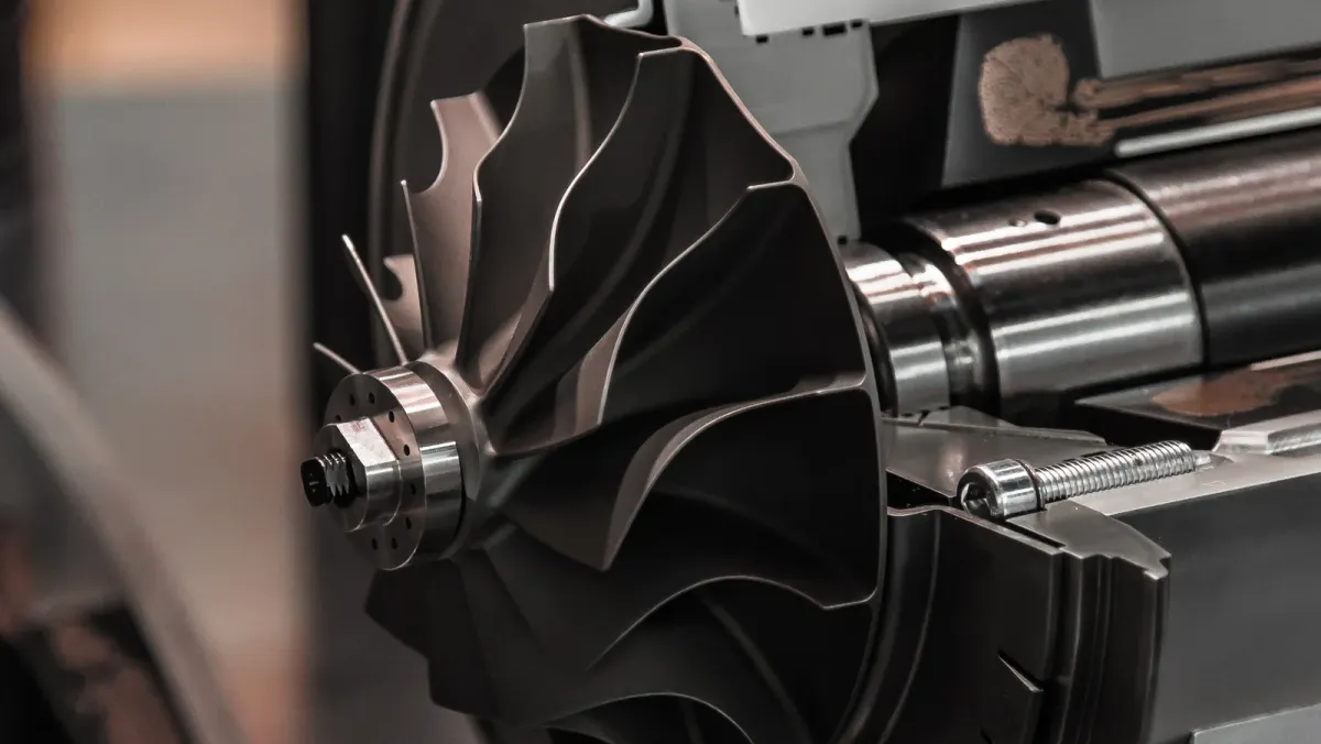
As the moving gas expands through the precisely contoured internal volute of the housing, it hits the turbine blades, converting thermal and kinetic energy into high-speed rotational power. Because the turbine wheel is locked to a solid forged steel shaft, the compressor wheel on the opposite side spins at the identical velocity. The spinning compressor wheel draws in ambient air, flinging it outward at extreme speed. This air passes through a static diffuser that slows down the airflow, converting velocity into static boost pressure. This dense, oxygen-rich air is then cooled by a charge air cooler before entering the engine cylinders, allowing more fuel to burn completely.
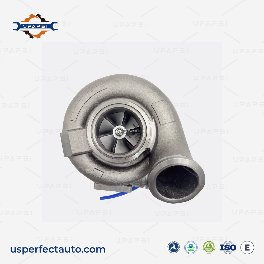
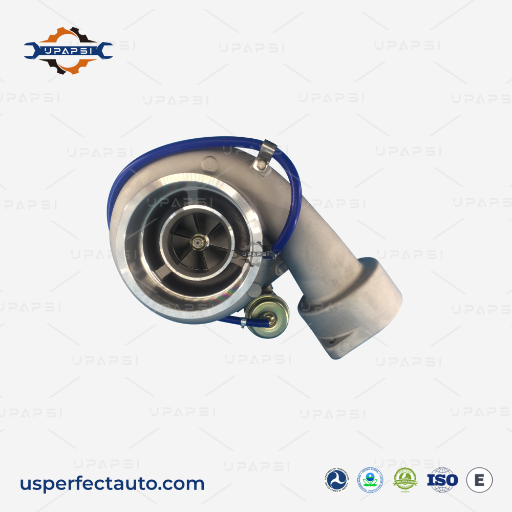
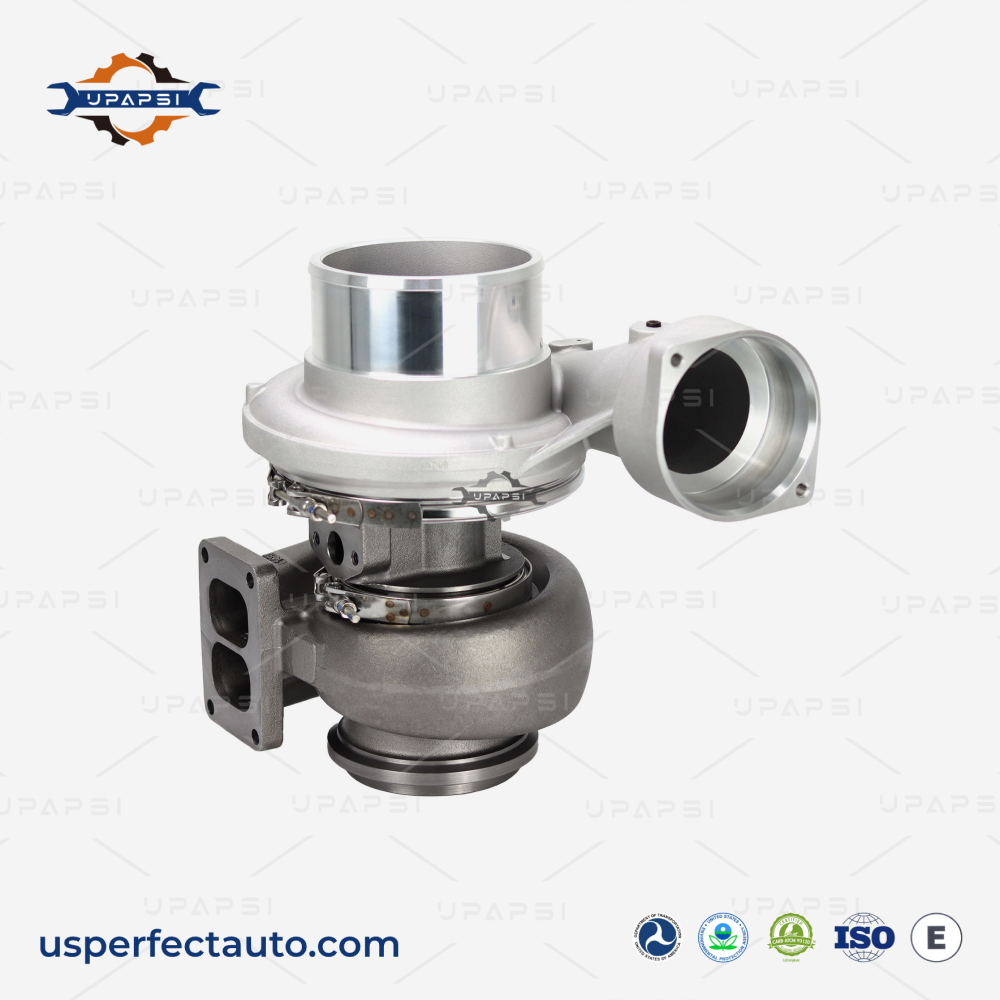
The Core Components of a Heavy-Duty Turbocharger
Industrial turbochargers are built from three primary structural assemblies working in absolute synchronization:
- The Turbine Section (Exhaust Side): Acts as the energy harvester. Constructed from high-nickel alloys (such as Inconel) to withstand continuous thermal loads exceeding 700°C without metal fatigue or cracking.
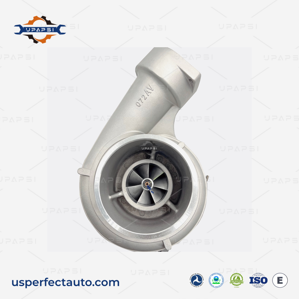
- The Compressor Section (Intake Side): Acts as the air pump. Typically contains an aerodynamic billet aluminum or titanium compressor wheel engineered to compress massive volumes of atmospheric air efficiently.
- The Center Housing Rotating Assembly (CHRA): The mechanical core supporting the connecting shaft. It contains full-floating journal bearings, thrust bearings, and targeted oil galleries. A continuous film of pressurized oil keeps the shaft floating to prevent metal-on-metal friction at rotational speeds surpassing 100,000 RPM.
Key Architectural Differences: Diesel vs. Gasoline Turbochargers
Heavy-duty diesel turbochargers face completely different operating environments than passenger car gasoline turbochargers. This divergence shapes their material selection and structural engineering:
| Engineering Vector | Heavy-Duty Diesel Turbochargers | Passenger Gasoline Turbochargers |
|---|---|---|
| Exhaust Gas Temperature (EGT) | Lower (typically 700°C – 800°C). | Significantly higher (up to 1000°C). |
| Continuous Boost Demands | Extremely high, sustained boost periods under steady loads. | Intermittent boost bursts during acceleration phases. |
| Material & Design Focus | Thick, heavy cast-iron or steel housings optimized for high-mileage structural integrity. | Ultra-high temperature superalloys to prevent thermal cracking under rapid temperature spikes. |
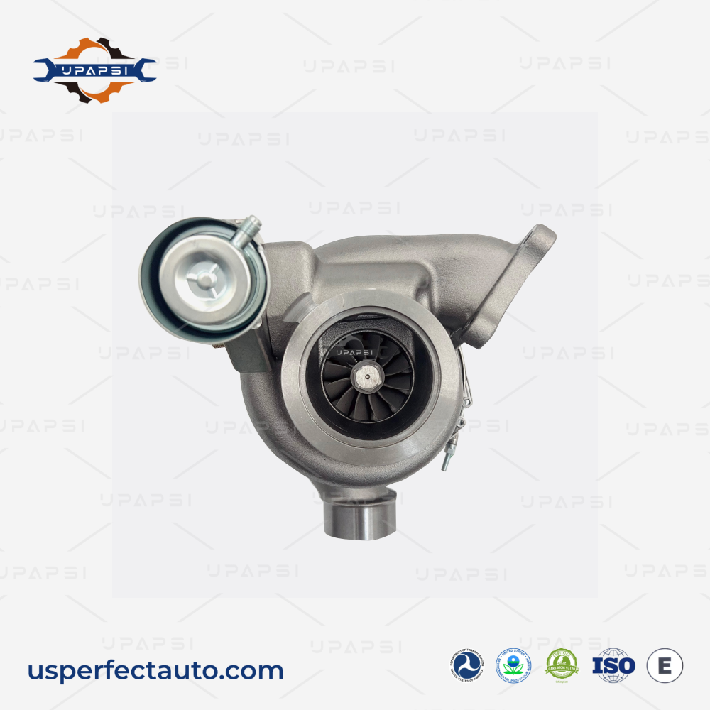
VGT vs. Fixed Vane Turbochargers
In the heavy-duty sector, turbochargers are broadly divided into fixed vane designs and Variable Geometry Turbochargers (VGT). Fixed vane systems feature a static interior housing volume, meaning they rely purely on engine RPM to build exhaust speed. This often results in noticeable low-end turbo lag and lower efficiency at low engine speeds.
Conversely, a Variable Geometry Turbocharger utilizes an internal ring of movable aerodynamic vanes positioned around the turbine wheel. An integrated electronic actuator adjusts these vanes in real-time. At low engine speeds, the actuator narrows the vanes to restrict airflow, speeding up the exhaust gases so the turbo spools almost instantly. At high engine speeds, the actuator opens the vanes to prevent over-boosting and lower backpressure, optimizing thermal efficiency across the entire power band.
Common Technical Misconceptions in Fleet Operations
A frequent misconception among fleet technicians is that "low boost pressure always points to a broken turbocharger." In reality, the turbocharger is a reactive system. If an engine has leaking air intake hoses, a cracked exhaust manifold, or worn components like an aging fuel injector or a leaking cylinder head, the turbo will lose the exhaust mass flow needed to build proper boost. Replacing a functional turbocharger without checking the complete intake and exhaust loops leads to repeated component failure and wasted maintenance budgets.
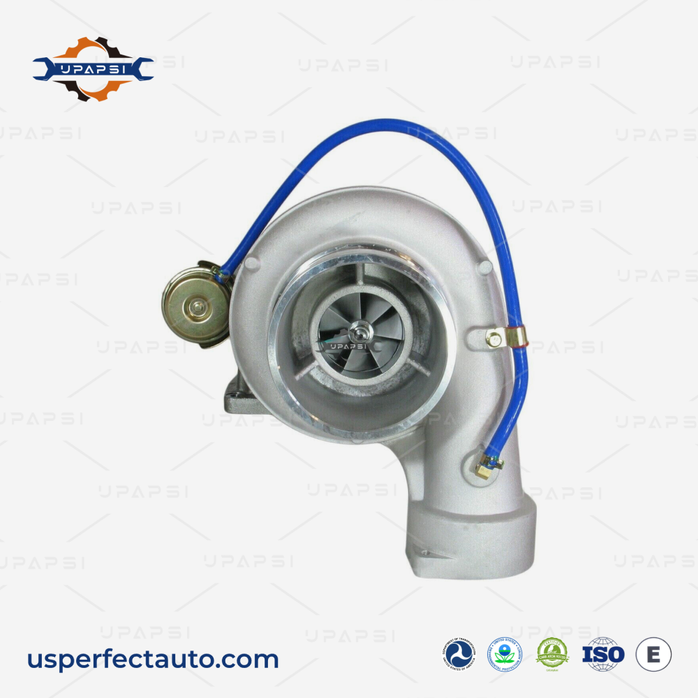
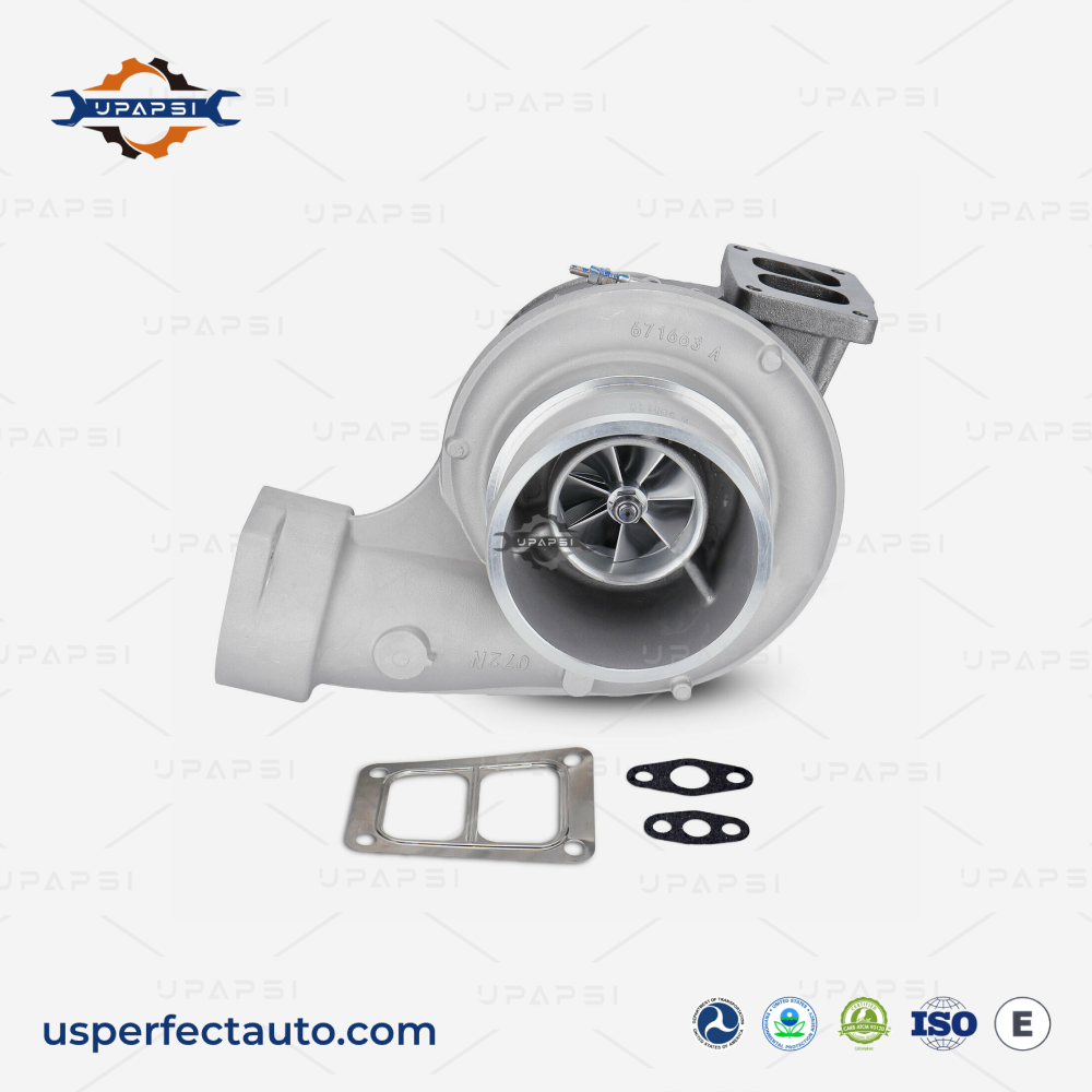
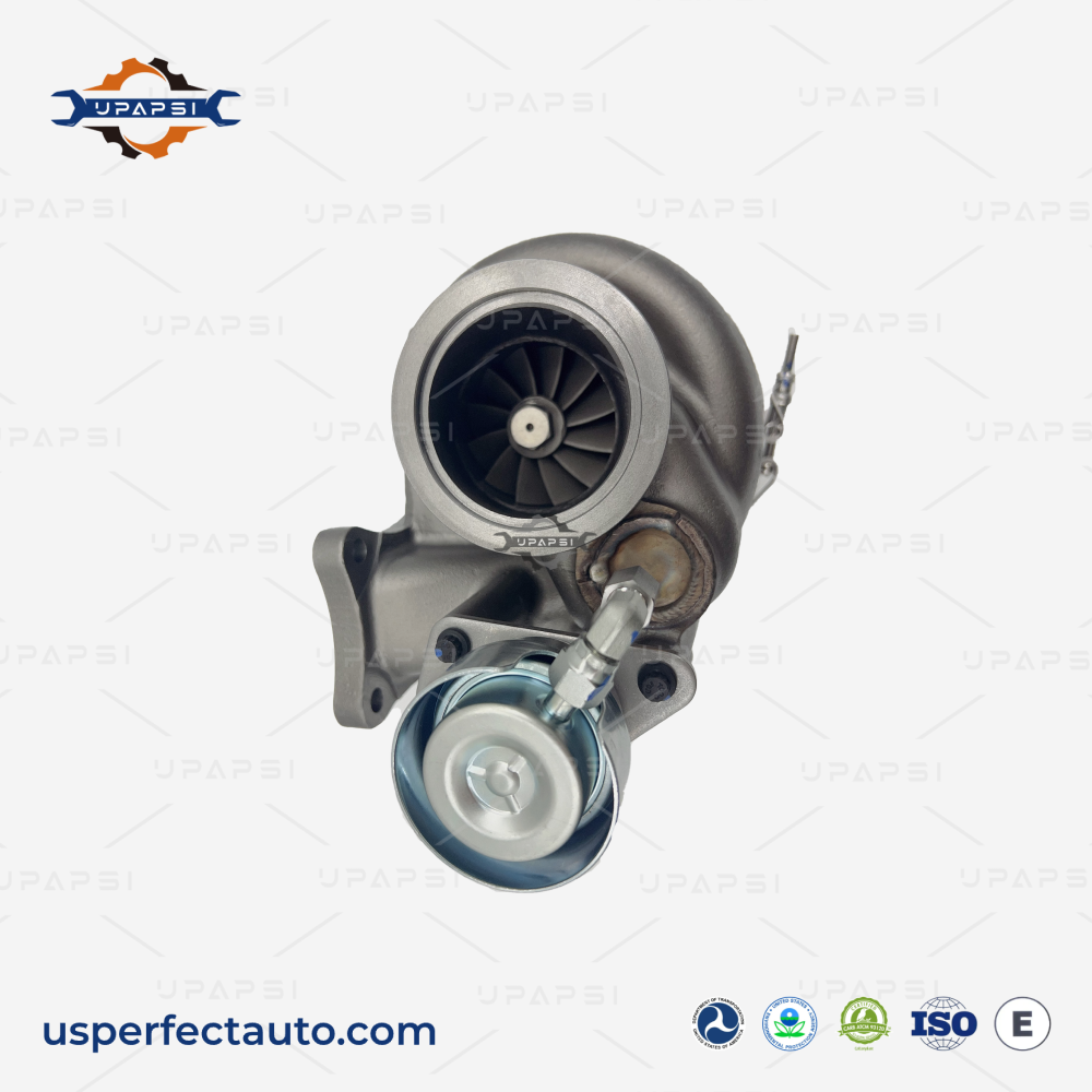
Premium Heavy-Duty Replacement Components
Maintaining high fleet uptime requires sourcing replacement components manufactured to exact OEM tolerances. We specialize in providing heavy-duty, field-tested components designed for maximum durability under extreme operational cycles:
- High-performance aftermarket Cummins turbochargers engineered for long-haul durability.
- Precision-balanced replacement Detroit turbocharger assemblies built to minimize mechanical drag.
- Severe-duty Caterpillar turbocharger options optimized for demanding construction and industrial applications.
Contact our technical team today to source verified replacement turbochargers, heavy-duty cylinder heads, and precision components tailored for your commercial fleet operations.
FAQ
Diesel turbochargers operate under lower exhaust gas temperatures (700°C–800°C) but require sustained high boost pressures over long periods, necessitating heavy-duty cast iron housings. Gasoline turbochargers experience much higher temperatures (up to 1000°C), requiring expensive high-nickel superalloys to resist extreme thermal cracking during short, intermittent boost bursts.
Fixed vane turbochargers feature a static housing profile that depends entirely on engine RPM to generate exhaust gas velocity, causing low-end turbo lag. Variable Geometry Turbochargers (VGT) use an integrated electric actuator to adjust movable internal vanes in real-time, optimizing exhaust gas velocity for instant spooling at low RPM and low backpressure at high RPM.
Blue smoke is a definitive sign of burning engine oil, indicating failed dynamic turbo seals or high crankcase pressure restricting oil return from the CHRA. White smoke typically signals a coolant leak into the combustion chambers or exhaust housing, which requires immediate engine diagnostic inspection to prevent hydrostatic lock.
Yes. A cracked cylinder head or blown head gasket allows cylinder compression to escape, directly lowering the pressure, thermal energy, and overall mass flow of the exhaust gases reaching the turbine wheel. This directly causes reduced turbocharger boost, slow throttle response, and low power codes.